Sunday 19 May 2013

Finished Circuit

18/05/13
After on more day of soldering the circuit board is finally finished.

Below is the finished circuit. As you can see the final connections have been made from the relays. I also used some heat shrink and drilled some holes through the board to feed the wires under and make it nice and neat.
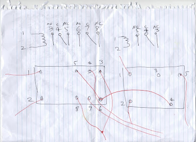
 To be more specific, pins 4 and 7 of the DPDT have been fed through a hole that was drilled and connected to the two terminals on the left of the board. This will allow one motor to the switched. The same process has been repeated for the other DPDT except they have been attached to terminal 3 and 4. This will switch the second motor's direction. The 5th pin of the SPDT relay (furthest in picture) has been fed through another drilled hole and soldered to terminal 5. This will control the servo. The 6th terminal has been connected to the positive terminal (green curved wire). Next on both DPDTs pins 3 and 8 have been fed through a big hole drilled out and stuck together with heat shrink and connected to the positive terminal to supply power. Pin 5 on the two SPDTs (for the motors) and pin 4 for the servo SPDT have been connected to the negative terminal through another drilled hole. This will complete the motor circuit. The final connections made were from the motor/servo circuits, to the arduino microcontroller. By reference of an image of the uno, pins 2-6 were soldered to the resistors to join the arduino to the motors. Pin 7 was connected to what will be the white wire of the servo  (or the left pin).The red pi of servo (centre) was connected to the 5V pin of the arduino and the black wire (right pin) was connected to the ground of the arduino. Finally, the other ground of the arduino was connected to the negative terminal. (to make reference to the relay pin numbers go to the picture below the bottom of circuit image.


The final thing left to do was to check that the circuit functioned by connecting it to power but before risking smoking popping out of the relays, the circuit had to be checked. The rough circuit layout below was drawn for this purpose checking and ticking off correct connections. Only one mistake was found. The negative terminal was supposed to be connected to the ground of the arduino, but I interpreted the image wrong and soldered it to the wrong header pin. This was quickly fixed and after plugging the circuit into power it functioned as required =D

Next weekend I will be beginning the programming phase.

Sunday 12 May 2013

Putting together the circuit

11/05/13-12/05/13
After two days of some intensive, soldering and wiring, the circuit board is near completion which means programming will begin soon.

In short, I have repeated the "Motor circuit" two times for each motor. I have then done it a third time but instead of using both a DPDT and SPDT relay, I have only used a SPDT which will be running the servo. The arduino uno is connected to the board using the 40 pin strips which have been snapped into pieces to match the arudino. Another small single 3 pin strip has been soldered in for the servo to plug into (position A20). In the circuit the relays have been taped together and then stuck to the experimenters board using double sided tape.

Top: Heat shrink was used to keep the wires already connected neat (so far thats only the 1s and 2s of the relays so its still a mess of wire)

Bottom: A hole was drilled on the top centre to allow the positive wires to feed from the relays to under the positive terminal block. The band side of the diodes have been bridged and also been connected to the positive terminal block to act as a block for back EMF.The transistors have had their centre base pin attached to the resistor. The emitters of the transistors has been bridged and joined to the negative terminal block. The pin connected to the arduino's ground has also been connected to the negative terminal. Each collector of the transistor has been connected to the 2nd pin of the relays (each fed through a hole which was drilled) and the other side of each diode.

 Relay Wiring: Diagram of the DPDT and SPDT relays and how they have been wired (numbers correspond the "motor circuit diagram". This was repeated twice for the pairs of DPDT and SPDT relays. The single SPDT relay for the servo simply has all pins with single wires running out of them except for 3.

Motor circuit diagram (x2):

Buying parts

5/05/13
Today I went to stop down at jay car to pick up my parts. The general order is below:
  1. Rainbow cable (2 metres)-WM4516
  2. Relay (x3)-SY4050
  3. Relay (x2)-SY4052
  4. Motor (x2)-YG2732
  5. Diode (100V, 150mA) (x5)-1N4148
  6. Pulley Set Small (x2)-YG286
  7. A Cradle Relay (For electromagnet, not sure about part number just picked a random one off shelf)
  8. Photo interrupter (x1)-ZD1901
  9. Transistors (x5)-BC548
  10. 4K7 Resistors (x2 packs)-RR0588
  11. Terminals (x10)-HM3130
  12. 40 Pin Single row header strip-HM3212 
  13. TGY09S Turnigy Micro Servo (x1)(Not from Jaycar)
  14. A bunch of heat shrink tubes
  15. Arduino Uno (x1)(Not from Jaycar, too expensive)
  16. Experimenters board (200x80-dimensions in mm) (Not from Jaycar)

Planning my circuit

4/05/13
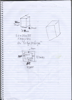
I spent today trying to draw up various diagram of what the circuit I will be constructing will look like, how the motors will run etc so I can get a rough idea of what to buy. Another major change is, instead of using two motors on the x-axis, I will only be using one to drive a pulley system. A photo interrupter will be used with it to act as a sensor for where the robot is locating its lowering arm (string with electromagnet). Some snipets of my scrap book plans are below:


Building the robot's shell

28/04/13
Today I built the structure of the robot. The pictures are underneath with the motors labelled. D will be a micro servo, c will be a motor, a will be a motor, b will be a motor:


Starting out

27/04/13
For my IPT major project I have decided to make an automated warehousing solution for a hypothetical company which stores and delivers refrigerators and freezers. It should pick up a fridge, store it in an available space on the storage grid and record that spot on the computer. When asked to retrieve an item, search for its coordinate and return it to the pick up point. In this blog I will cover the development of the scaled prototype of the robot from start to finish, but not the documentation.

In more detail it will require a:

  • X-axis (Driven by two motors)
  • Y-axis (Driven by one motor)
  • Z-axis (Driven by a servo which lowers a string)
  • An electromagnet (Magnetises to pick up a steel plate attached to the top of the box (hypothetical fridges)
It will most probably be made out of lego, and be programmed using an Arduino Uno.